A Complex Cost Picture
Energy efficiency offers the most LEED points and the most opportunity for operational cost savings. Getting there can mean design and construction cost premiums. But with an integrated process and use of smart load-reduction strategies, some LEED projects wind up with first-cost savings, and many projects with cost premiums have favorable payback periods.
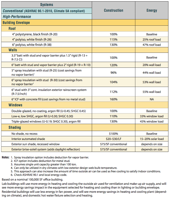
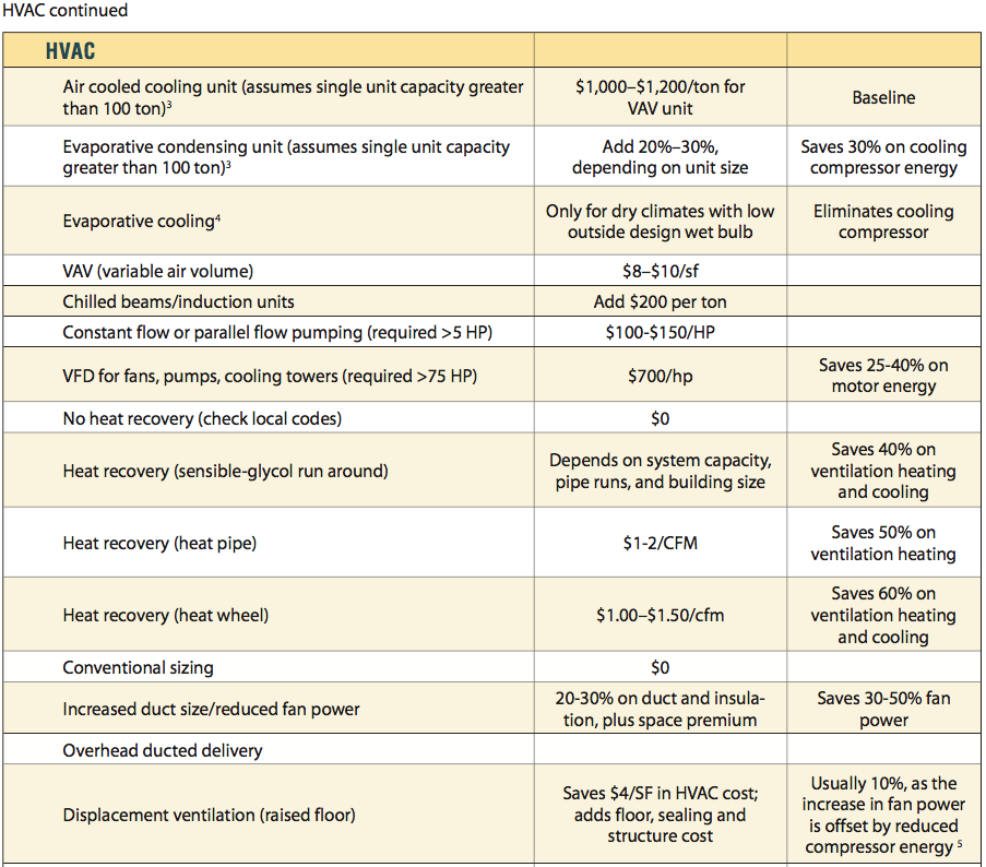
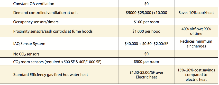
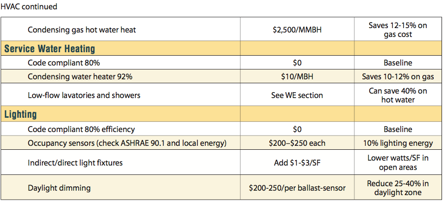
Because of the interplay of these factors, our table for construction cost premiums also highlights energy savings where figures are available. Although many of these strategies come with apparent cost premiums, it bears repeating that cost premiums for items like efficient glazing can lead to cost savings on mechanical system sizing, for example.
In order to constrain the scope of this study, the building elements and systems listed below represent a selection of strategies that can be applied to standard office buildings depending on size, climate, and building systems.
As ASHRAE updates Standard 90.1 in its regular update cycle, and codes and standards generally increase, what were previously energy saving strategies become standard requirements. With “low-hanging fruit” increasingly picked up in codes, there is all the more reason to use an integrated design process where designers work closely with insightful energy modelers and engineers.
Soft Costs
Energy modeling fees are driven by building size and system complexity, and will vary
by the amount of time needed and number of different modeling cases needed. Fees generally start around $4,000–$6,000 for smaller, less complex projects, such as a core/ shell office or retail structure up to approximately 15,000 ft2, or a tenant fit-up of 12,000 ft2.
A 50,000–100,000 ft2 office core/shell energy model could cost $10,000–$12,000, while
a similar build-to-suit office could range from $15,000–$18,000. Lab and medical occupancies will always be more involved, reflecting increased fees as much as 25% above similarly scaled office buildings.
Dormitories and apartment buildings may also require more complex modeling due to the smaller capacity (and therefore, larger quantity) of the terminal systems used, along with the fact that a different baseline system must be used.
As with construction costs, you’ll get out of your investment in energy modeling what you put into it. If following the performance path for this credit, you’ll be running, at a minimum, two energy modeling simulations (one for the “baseline” case and one for the building as designed) near the end of the design process.
While that approach will meet the LEED documentation requirements, and provides useful information for both the design team and eventual property managers, it acts as more
of a scorekeeper than a game changer. Rather than merely being a tool which measures decisions being made at the end of the project, modeling software can be used iteratively to show the energy impact of using different types of glazing, insulation, HVAC systems, lighting designs, and more.
Done early and often during the design process it can inform key decisions, particularly when comparing short-term costs to long-term paybacks on more or less costly building elements or systems.
There is a reason that more projects don’t do iterative energy modeling: adding design options can quickly multiply the number of modeling runs needed, and these take time. An experienced, integrated team will conduct simpler modeling runs early, and later complete complex ones, all while informing key design decisions.
Utility Incentives
Many utility incentive programs require energy models similar to LEED, with a baseline and a design case.
Although in theory this can help pay for modeling, documentation required by utilities is typically different from LEED.
For LEED, the model is typically created by inputting the design case, and then reducing all the regulated element values and efficiencies down to match minimal energy standard compliance for the baseline case.
Utilities usually ask for the baseline to be created first using the actual project geometry, followed by the design case, which is created by incrementally adding each energy conservation measure (ECM) as a separate parameter so that the final model has all ECMs collected together in one aggregated run. This enables the utility to analyze each ECM to make sure it passes its mandated cost/benefit ratio.
The good news is that the utility incentives paid generally takes the additional energy modeling into account, and utilities tend to cover up to 50% of the cost of developing modeling for rebate purposes.
Additional Approaches
In addition to the strategies shown in the table, other approaches worth mentioning are underfloor air distribution systems (UFAD) and combined heat and power systems (CHP). Each strategy illustrates how closely strategy selection is tied to effective process.
UFAD systems supply conditioned air from beneath a raised floor using automatic
or manually operable floor diffusers, which can increase user comfort by granting controllability of their environment. These systems take advantage of natural upward heat convection currents from occupants and office equipment in the space, as air travels in one direction up towards the ceiling return. Standard ceiling supply systems blow supply air against this natural convection current, creating turbulent mixing conditions within a space.
For this reason, UFAD system supply air temperature is warmer (60°F–62°F) than standard ceiling supply air systems (53°F–55°F). This reduces refrigeration load in the cooling season while enlarging the temperature window during which outdoor air can be used for cooling with an economizer.
Due to warmer supply temperature, UFAD systems need a larger quantity of supply air to deliver the same amount of cooling, resulting in higher fan horsepower; however, the reduction in refrigeration energy use generally outweighs the increased fan operation energy use. UFAD system fans generally operate based on maintaining a static pressure setpoint in the space below the floor; therefore, tight sealing of the floor and walls around the plenum is critical for correct operation in order to maximize energy savings.
Combined heat and power systems (CHP) use fuel to create electricity and then use the waste heat in the building. For example, a system could use an engine generator or micro- turbine to generate electricity and then capture the cooling water heat and exhaust heat to make chilled water, heating water, domestic hot water, or some combination of all of these.
CHP systems are most cost-effective when all electricity and all waste heat is used in
the building all year long. For example, a community center uses power for lighting and electrical systems and domestic water heating for laundry, showers and/or pool heating. Any heat not used must be rejected outdoors or to cooling water, which adds cost for heat rejection and reduces the economic viability of the system. This makes it important to “right-size” the system for continuous loads and not select a system based on expected or calculated peak operation.
Cost Synergies
SSc5: Heat Island Reduction
SSc6: Light Pollution Reduction
WEp2/WEc2: Indoor Water Use Reduction
EAp3/EAc3: Energy Metering
EAp4/EAc6: Refrigerant Management
EAc5: Renewable Energy Production
EQp1: Minimum Indoor Air Quality Performance
EQc1: Enhanced Indoor Air Quality Strategies
EQc5: Thermal Comfort
EQc6: Interior Lighting
EQc7: Daylight
Minimum Energy Performance
10% New Buildings or 5% Existing Building Renovation


