

Forum discussion

NC-v4 EAp2:Minimum energy performance

Baseline pressure drop adjustments

Hi all,

I've got a question about calculating the pressure drop adjustments for a baseline building. I'm using LEED v4, ASHRAE 90.1 2010.
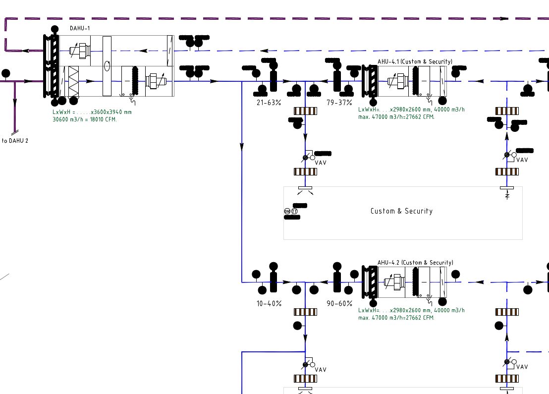
 

The proposed case has a DOAS ahu that supplies fresh air and 2 AHUs that recirculate air for cooling. The DOAS has MERV 7 and MERV 14 filter on the supply side and a MERV 12 filter on the return side. The recirculating AHUs have a MERV 12 filter. There are 3 similar systems like the schematics above. I'm supposed to calculate the pressure drop adjustments for the air flow passing through each section. Supply air is around 96000 L/s and fresh air is around 25000 L/s, which means around 24% goes through MERV 7+MERV 14 filters and 100% L/s goes through MERV 12 filters. MERV 7 filters are not specified so I can't take pressure drops for these.

The baseline has around 70790 L/s of supply air flow and 13580 L/s fresh air.
I've added it to the calculator as below but I'm not sure if this is correctly interpreted.
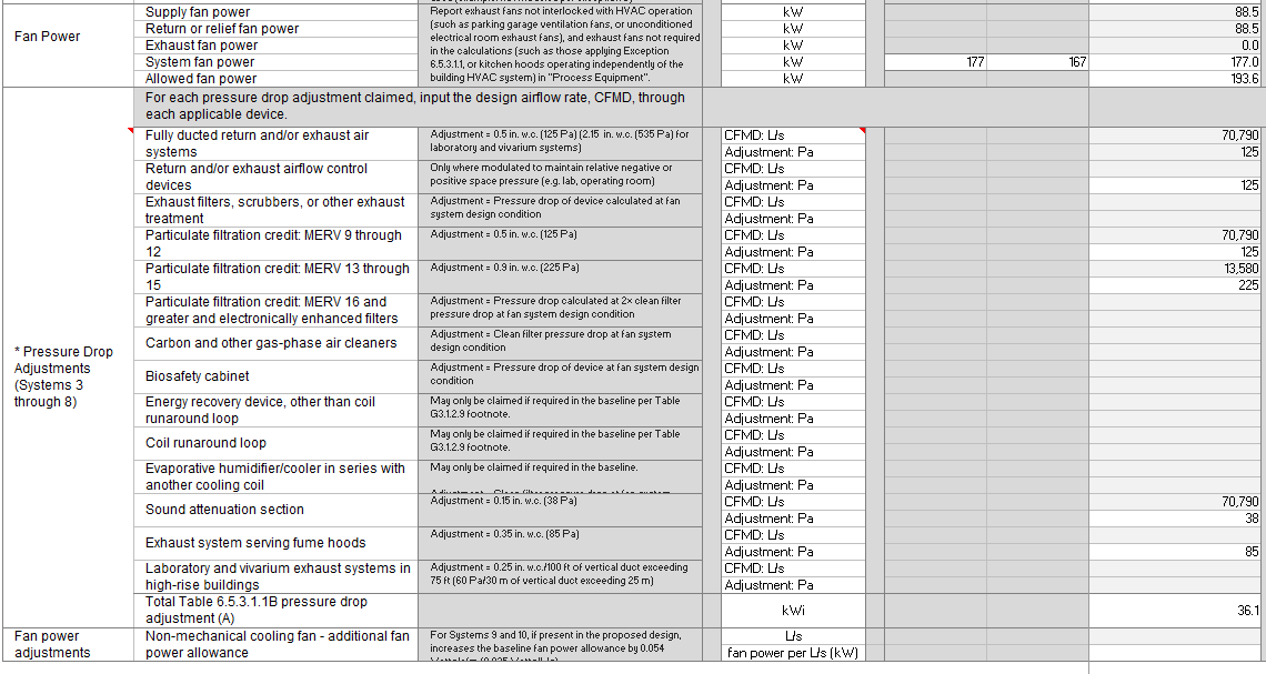
 

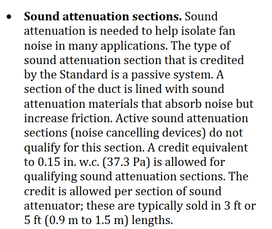
Second, I have 2 sound attenuator sections in my ducts on the supply side and 1 on the return side. How do I apply this to the calculator? I'm allowed to take credit of 38 pascal per sound attenuator section, however since they are not the same for the supply and return I'm not sure how to add this in the sheet. Also I can't change the 38 pascal in the sheet, do I multiply my airflow x2 in that case and how do I differentiate between supply and return?
Anyone who can guide on the approach here?
Thanks in advance!

Kind regards,
Boris Jonjic


0

You rely on LEEDuser. Can we rely on you?

LEEDuser is supported by our premium members, not by advertisers.

Go premium for $15.95  »

Fri, 08/07/2026 - 08:19

Quick add on. One of the AHU's actually has a MERV 12 in series with MERV 14 on the supply side and a MERV 12 on the return side.

Mon, 08/17/2026 - 02:34

Hi Boris, thanks for sharing this. It’s an interesting setup, and I haven’t worked with this exact DOAS and recirculating AHU arrangement before.Would you mind clarifying where the two supply-side and one return-side sound attenuation sections are located relative to the mixing points? Do you also have the individual design airflow through each section?For the AHU with the MERV 12 and MERV 14 filters in series, do you know that AHU’s individual design airflow? I’m trying to understand whether the pressure-drop adjustments should use the total baseline system airflow or the airflow through each individual branch.Thanks!

Wed, 08/19/2026 - 14:59

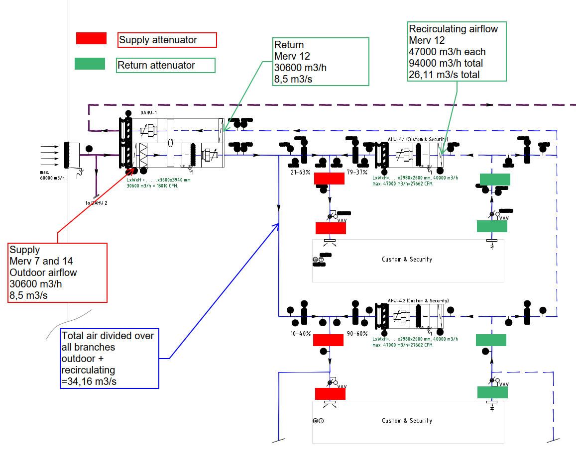
Hello Joo-yeol Lee, thank you for your reply. It's also my first time dealing and modeling a system like this one.I've tried to illustrate your question in the schematics below. I mistakenly mentioned that there were 2 attenuators on the supply and 1 on the return side. It's either 2 or 1 on both supply and return depending on the system.System 1, DOAS with Recirculating unit. The air flow is split up into 2 branches. Each branch has 2 attenuators on supply and 2 on return. System 2: DOAS with recirculating unit. Identical to system 1, though slightly higher airflows and only 1 sound attenuator on each branch.System 3, 100% outdoor air, with 1 sound attenuator in ducts, and a Merv 12 + merv14 in series on supply and Merv 12 on return. 1.
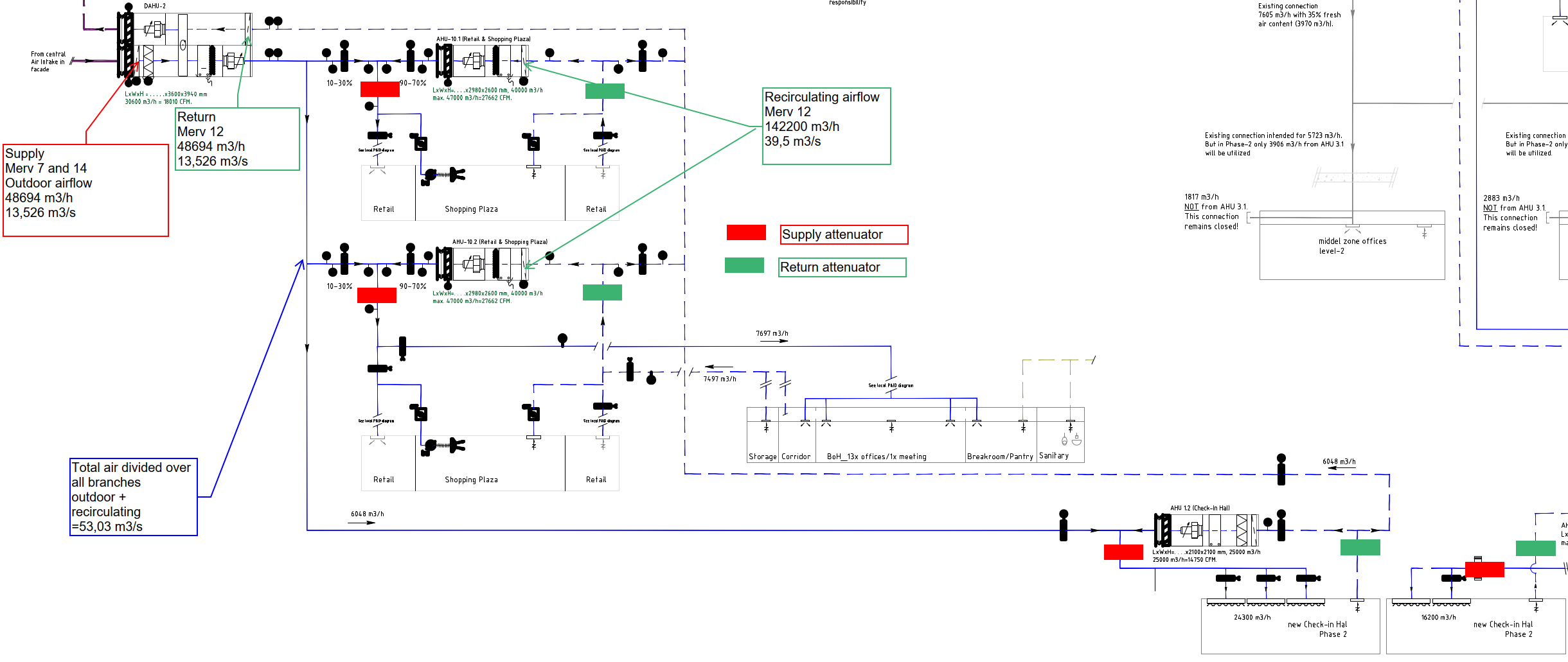
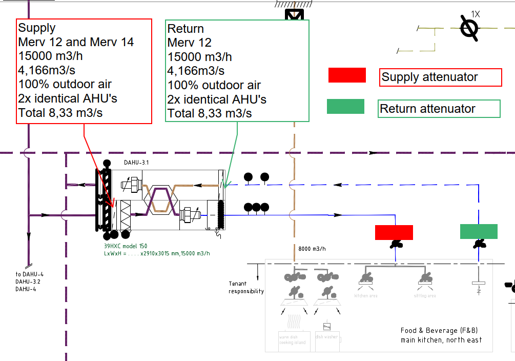
So for the sound attenuators I believe I should calculate proportionally with 2 attenuators only over the airflow going through system 1. And 1 sound attenuator over system 2 and 3. System 1 is around 30% and system 2 and 3 are around 70%. That would mean 30% of baseline airflow should have two attenuators and 70% only one. Would you agree? And how should I add this to the MEPC sheet? 
I believe 70% of baseline airflow + 2x30%, so 130% of baseline airflow should work then.2.
For the filters it seems a bit more trickySystem 1 and 2 have 100% Merv 14 on supply and 100% Merv 12 on return. 
In system 3, 100% of supply goes through Merv 12 and Merv 14 in series. And 100% of return goes through Merv 12.
System 3 is around 10% of the total airflow.Not sure how to add this to the MEPC sheet, but I believe something like this.
100% of supply goes through Merv 14. So 100% of baseline airflow can be added to the pressure drops here.
100% of return goes through Merv 12 + 10% through supply. So total 110% of baseline airflow can be added to the pressure drops?Not sure if this approach is correct. If it is, then I'm wondering if I can 2x the baseline supply air flow for the fully ducted supply and return part, since the baseline airflow goes 100% through supply as well as return, though I've never done that before and it feels wrong. 

I hope I've explained it clearly, if not please let me know. Many thanks for your help.

Kind regards,
Boris Jonjic


Wed, 08/19/2026 - 15:02

I see the formatting of the text and pictures changed after posting this. I hope it's still readable.

Add new comment

To post a comment, you need to register for a LEEDuser Basic membership (free) or login to your existing profile.